Surface finish metrology
- Surface finish is a qualitative parameter and it is qualitify with the help of the roughness parameter.
- Any machine component will have a certain amount of irregularities which is responsible for appearance on the component.
- When a component having a large number of irregularities which said to have a poor surface finish on the other hand small amount of irregularities present on the component's surface is considered as mirror-like surface finish.
- The different type of irregularities present over the machined component is broadly divided into two categories
Microscopic irregularities
Macroscopic irregularities
- The area which can't be identified by the normal human eye is known as microscopic irregularities
- The irregularity which can be identified by the human eye is known as macroscopic irregularities
Roughness-
it is a small wavelength irregularity present over the machine component it is also known as the primary texture of components in since roughness can't be identified by normal human eyes, therefore, it is considered as microscopic irregularities
it appears due to wrong selection of cutting fluid, improper selection of feed and depth of cut during machining
it appears due to wrong selection of cutting fluid, improper selection of feed and depth of cut during machining
Waviness-
If large wavelength irregularity present over a machine component it is considered as the secondary texture of the component. since it can be defined by normal human eyes, therefore, it is kept in the category of microscopic irregularities.Waviness appears due to error in the component like the error in the guide base, error in the lead screw, Error in the cross slide machine, Machine vibration, Tool vibration (chatters), etc.
Apart from roughness and waviness the other two types of irregularities present over the machine component are-
ley is a predominant feed mark produced by the tool over the workpiece for standard machining operation.
The flaw is surface imperfections such as blowholes cracks porosity etc present over the machine component at random location without following any standard pattern measurement of roughness step followed As given below
 |
| Types of lays |
Measurement of roughness by follow the steps given below-
First step-
Identify cut off length it is the length of work is upon which the office analysis is to be performed.
Second step-
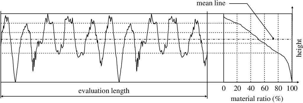
Identify the reference pattern for joint over the workpiece and plot the roughness profile.
Third step-
Stablished a reference line for that some line the reference line is to be established by the following two standard systems.
- E-System
- M-System
Envelope system-
In this system a ball of 25mm is rolled over the component and locus of center of the ball is continuously addressed by the joining the locus of center and envelop can be phone found the envelope should be move-in upward or downward direction in such a way that the area is equal to area below the envelope in this case envelope is considered as a reference or inline system in this system a straight line is drawn in such a way that the area above line is equal to the area below the line this area is considered as reference line or min line
Fourth step-
After setting the reference line mean line can be determined by the four methods
- Maximum height of roughness or peak to valley height
- The average height of roughness or Central line average value the
- Root mean square value RMS
- Ten-point Average values


0 Comments
Thank for Visiting our site
we will Happy to see you here again